
Fault Location: Four devices go head-to-head
Fault Location: Four devices go head-to-head
Last year an Asian transmission utility invited four companies to demonstrate the capabilities of their travelling wave fault location systems. Five tests were carried out over three days with one clear winner at the end.
The fault location demonstration
In autumn of 2012 four companies were invited to demonstrate their “travelling wave” fault location devices by an Asian utility. The demonstration would take the form of a test where the utility would induce five faults at different locations on a live 115 kV transmission network. Each company would have two days to install their equipment and on the third day the faults would be induced. On that third day the four companies would be placed in a room with remote access to their devices. As each fault occurred they would be asked to communicate to their respective units and give the “distance to fault” (DTF). The live faults were performed on 13th of May 2012.
One of the devices – Qualitrol’s latest generation TWS FL-8 travelling wave fault locator – consistently gave the most accurate results for each of the five faults. The TWS FL-8 located three of the faults to within 45m. While the accuracy of the TWS FL-8 on the fourth fault was 300m, it was still more accurate than the competitors by a factor of two. On the fifth and final test (high resistance fault) Qualitrol’s TWS FL-8 was the only device to trigger and capture the fault. In this simulation the line did not trip, however the FL-8 was still able to locate the fault, to within 268m (0.3% of the line length).
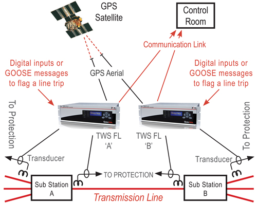
Figure 1: A typical double ended fault location setup
This article provides details on the tests performed, as well as the actual results from all four companies. Records, installation photos and master station screen grabs are taken from Qualitrol TWS FL-8 and iQ+ software.
Installation and the network
The five faults were performed on a 115 kV network. The single line diagram is shown below in Figure 2. The substation names have been changed to respect the utility’s request for anonymity. The faulted overhead line (shown in red) was reported to be 81.89 km long. Each of the four participating companies placed fault location devices in substation “A” and substation “B”.
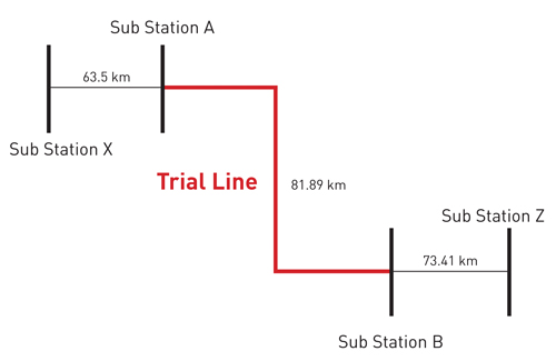
Figure 2: Network diagram
As each fault was created on the 115 kV circuit, high frequency travelling waves were produced. These waves spread out in each direction along the transmission lines eventually reaching the substations at either end. The units placed at each end of the overhead line would capture and time tag the arrival of the high frequency travelling waves. The time difference between the time tags from each end of the line would be used, along with the speed of the travelling wave, to work out the distance to fault.
Figure 3 shows how the TWS FL-8 captured the travelling waves by placing red split core linear couplers over cables feeding the current signals to the protection relay. The output from these red linear couplers were fed back to the input of the TWS FL-8.
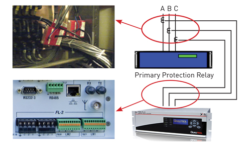
Figure 3: Qualitrol TWS-FL8 installation
Faults were induced using a high impedance rope attached to a low impedance thread. The high impedance rope was looped over the cable(s) of the overhead line. A line patrol engineer then slowly pulled on this rope until the low impedance section touched the cable and produced an arc.
Test 1 and calibration
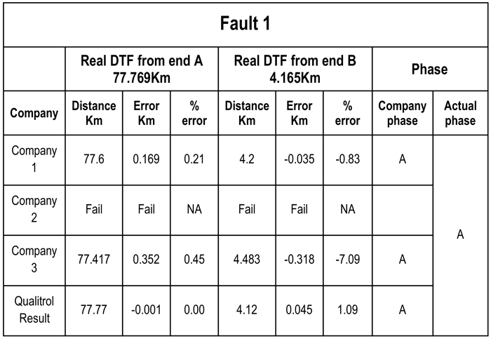
The first test took place at 8:31:33 in the morning. The results from the four companies and the actual distances to fault are shown in Table 1 below.
Table 1: Test 1 results, Qualitrol to within 45 metres
Qualitrol’s calculated distance to fault was to within 45 meters of the actual values quoted by the utility. Two of the other competitors give distances to fault as far out as 169m and 352m. The fourth competitor fails to capture signals due to equipment malfunction. They drop out of the testing.
The line length had originally been quoted as 81.89 km. However following a reclose, Qualitrol recalibrated the line length using single ended analysis. Figure 4 shows a screen grab again taken from Qualitrol’s iQ+ master station software. The time difference between the original pulse caused by the reclose and the reflected pulse received back from the far end of the line were used to calculate the real line length. In this case the real line length was measured as 81.93 km. This was later confirmed by the utility using Type A travelling wave detection.
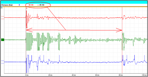
Figure 4: Qualitrol iQ+ showing test results
Three more tests followed
The second test took place at 9:18:11am. The results from the four companies and the actual distances to fault are shown in Table 2 below.
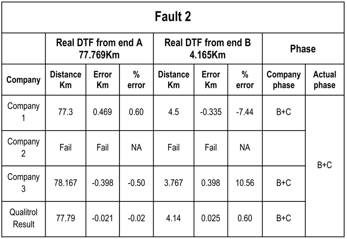
Table 2: Test 2 results, Qualitrol to within 25 metres
Again Qualitrol’s TWS FL-8 unit was the most accurate; giving a distance to fault that was to within 25m of the actual distance quoted by the utility. Other competitors were out by 496m and 398m respectively.
The third test took place at 10:34:06am. The results from the four companies and the actual distances to fault are shown in Table 3 below.
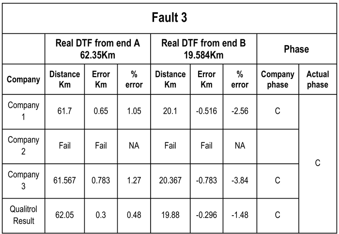
Table 3: Test 3 results, Qualitrol to within 300 metres
Qualitrol’s TWS FL-8 continues to outperform the competition. The FL8 gives the distance to fault to within 300m of the actual fault. This distance is two times more accurate than the other devices.
The fourth test took place at 10.59.11am. The results from the four companies and the actual distances to fault are shown in the Table 4 below.
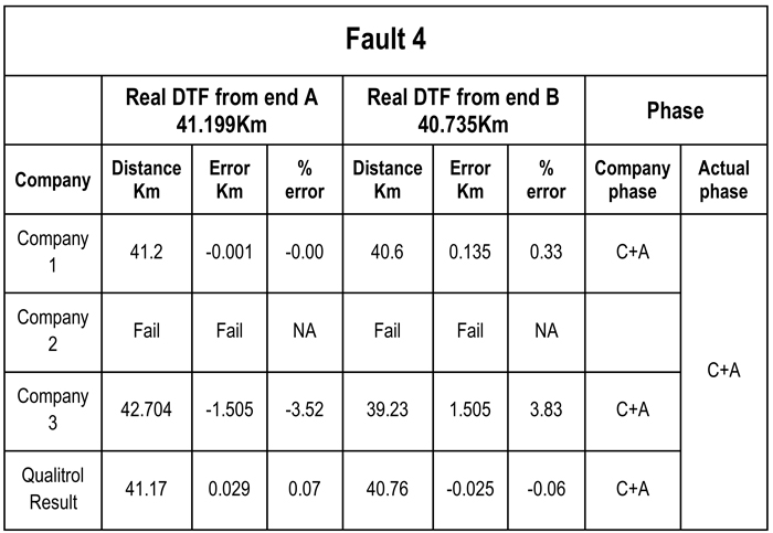
Table 4: Test 4 results, Qualitrol to within 25 metres
Qualitrol’s TWS FL-8 places the fault at 41.17 km from one end of the line and 40.76 km from the other. These distances are 29m and 25m away from the actual fault respectively. Once again the TWS FL-8 is the most accurate device.
The competitors’ quote distance to fault as far away as 135m and 1505m respectively.
The high impedance test
The fifth and final test was slightly different than the rest. It was an attempt to simulate a high resistance fault. The fault was induced using the same high impedance rope attached to a low impedance thread. However, this time rather than have the thread directly grounded to earth it was tied to a tree branch and the tree branch was pushed into the ground.
The rope was again looped over the cable(s) of the overhead line and a line patrol engineer slowly pulled on this rope until the low impedance section touched the cable and produced an arc. During this test the line being monitored did not trip. There was a lot of arcing but the branch simply burned right through with no flashover. With this information in mind the utility did not expect any of the units to trigger on this test. The results for test number five are shown in Table 5 below.
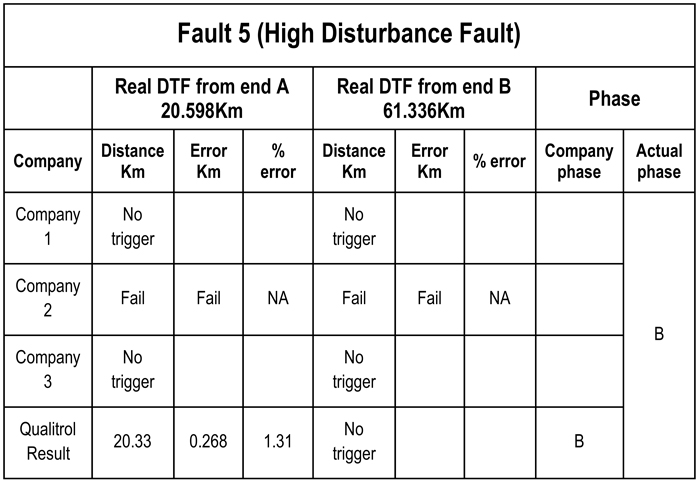
Table 5: Test 5 results, Qualitrol to within 268 metres
Qualitrol’s TWS FL-8 unit was the only device to trigger on this test. All other devices failed to capture any signal. While the FL-8 did not trigger on both ends of the line, it did capture the signal on one end. Using single ended analysis the distance to fault was given to within 268m of the actual fault distance. Figure 5 shows the record used for single ended analysis.
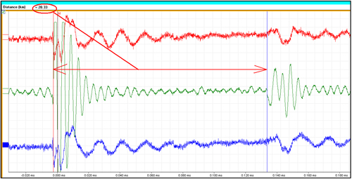
Figure 5: Single ended analysis of fifth and final fault
One of the flexible settings on the TWS FL-8 configuration is its trigger thresholds. For the duration of the testing, the TWS FL-8 trigger threshold had been set to 15% of the full scale deflection. See Figure 6.
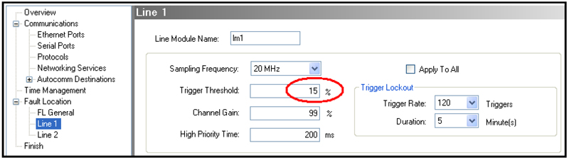
Figure 6: Setting the trigger threshold
This value could have been reduced to a lower value that would have allowed the TWS FL-8 units to trigger on both ends during test number 5. The test was not repeated at this lower threshold because one of the transmission line insulators had cracked during the previous fault.
For a full list of all TWS FL-8 results taken from Qualitrol's iQ+ master station software see Figure 7 below. Note the unit was set to capture the travelling waves at 1.25Mhz and 20Mhz.
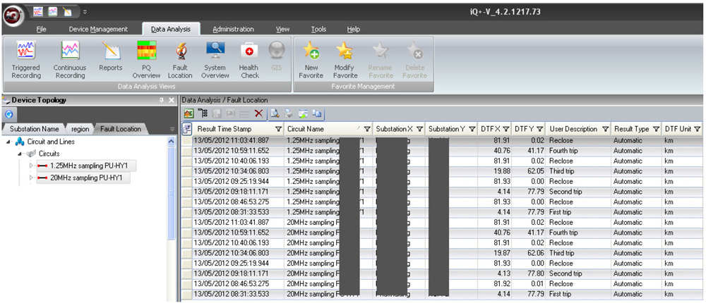
Figure 7: iQ+ screengrab showing fault location results
Qualitrol Expertise
The outcome of this utility demonstration clearly indicates the value of experience. Qualitrol has been supplying travelling wave fault location devices since 1992. In this time, over 1,500 fault location devices have been installed in 70 different utilities in over 30 countries around the world. Qualitrol has been the leader in fault location devices for over two decades. The new TWS FL-8 platform (the 7th generation device) continues to prove that Qualitrol is best in class when it comes to accurate, fast and simple fault location devices and software.
In Australia and New Zealand, Insulect have represented Qualitrol for over a decade and have successfully installed travelling wave systems in a number of transmission utilities, some of which have been in operation for many years and have proven their worth many times over.
Benefits for the utility
Travelling wave fault location is a very accurate method of locating faults on an overhead transmission line – whether these are permanent, intermittent or transient. Permanent faults are rarer, however they need to be found and fixed fast. A reliable travelling wave system makes possible accurately location and rapid resolution of a fault, resulting in significant time and cost savings.
Intermittent and transient faults were historically not taken too seriously. However there is an increasing awareness over power quality and system stability issues that are driving a need to reduce the number of line trips. Intermittent faults can be re-closed but can occur again, as in the case of damaged insulation or vegetation. Transient faults can also be re-closed and are caused by random events such as lightning and bush fires.
The high accuracy of the travelling wave method provides a solution to all these problems, including verification of fault cause, tracking intermittent fault problems and identifying damage caused by bird streamers.
To find out more about the travelling wave method of fault location or the Qualitrol range of fault location products,